


Description
Introduction
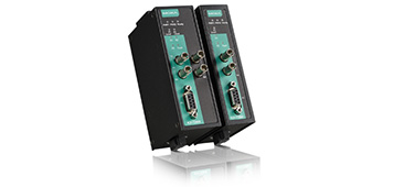
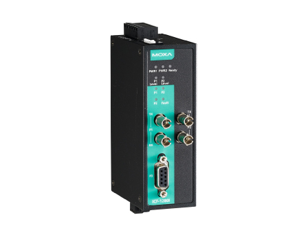
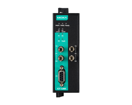
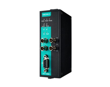
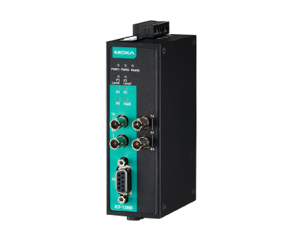
The ICF-1280I industrial PROFIBUS-to-fiber converters are used to convert PROFIBUS signals from copper to optical fiber. The converters are used to extend serial transmission up to 4 km (multi-mode fiber) or up to 45 km (single-mode fiber). The ICF-1280I Series provides 2 kV isolation protection for the PROFIBUS system and dual power inputs to ensure that your PROFIBUS device will perform uninterrupted.
Remote Fiber Diagnosis
Optical fiber cables are often deployed for long-distance communication and a fiber-optic inspection pen is used by engineers to ensure proper communication quality of the fiber cable. The ICF-1280I Series eliminates the need for a fiber-optic inspection pen by providing a Remote Fiber Diagnosis function that uses DIP switch adjustments.
There are two major functions provided by Remote Fiber Diagnosis: (1) determining which side (Tx or Rx) is causing the problem on the converter; (2) examining the fiber connections for the overall topology from any individual converter. Fiber cable abnormalities can be automatically detected and identified by the LED indicator even if it is not adjacent to the converter. Remote Fiber Diagnosis facilitates fiber cable deployment and management, and also significantly shortens troubleshooting time by examining fiber connections for the overall topology from any individual converter.
Redundant Ring
The ICF-1280I Series of converters can connect PROFIBUS devices in a redundant fiber ring topology. Use the DIP switch to configure all the ICF- 1280I converters to redundant ring mode. When a PROFIBUS master transmits a signal from one converter to the PROFIBUS slave devices, this signal will travel to all the converters around the ring until it returns to the original converter and terminate. The redundant ring structure ensures no packet loss with zero recovery time.

PROFIBUS Fail-safe
Electrical noise may be generated when a PROFIBUS device malfunctions or the serial interface fails, resulting in bus failure. Traditional media converters transmit noise signals through the fiber wire to the other converter. This not only disrupts data communication between the two buses, but will also bring communication across the entire system to a halt. When this occurs, the engineers will not be able to easily locate the failed device because the entire PROFIBUS network is down. To avoid this situation, the ICF-1280I Series has a mechanism to detect and recognize noise signals. If the bus fails on one side, the noise signal will not propagate through the ICF-1280I converter and affect additional bus segments. In addition, the ICF-1280I converter will also trigger an alarm to provide the location of the failure to the field engineer.

Auto/Manual Baudrate Settings
The ICF-1280I converters convert signals back and forth between PROFIBUS and fiber at baudrates between 9.6 kbps to 12 Mbps. Engineers do not need to know the baudrate of the connected PROFIBUS device; the ICF-1280I converters can automatically detect the baudrate of the PROFIBUS device and apply this baudrate directly. This is an extremely convenient feature. If necessary, baudrates can be set to a fixed value via DIP switches to shorten the baudrate detection period when the system initializes.
Fiber Link Monitor
The ICF-1280I converters support a fiber link monitoring function to detect communication errors on both sides of the fiber connection and determine which side (Tx or Rx) is causing the problem. When a communication error occurs, a red LED status indicator will turn on and the relay alarm will activate. If a fiber abnormality occurs at a remote fiber segment, the Fault LED will flash to indicate the abnormality was in the remote segment. Engineers can use the fiber test function for troubleshooting.
Fiber Signal Intensity Diagnosis
In some circumstances, you may need to measure the receive level of the fiber-optic port with a voltmeter, which can be connected while the device is operating (doing so will not affect data transmission). The measurement can be taken with a voltmeter and read on a PLC that uses floating high impedance analog inputs, which allow you to do the following:
- Record the incoming optical power for later measurement (e.g., to indicate aging or damage).
- Carry out a good/bad test (limit value).